The Idea
Gears are by far the most used transmission elements in mechanical systems. Though you can design and build a lot of robotic toys without dealing with gears, more sophisticated (cool!) designs will claim the use of specific gears. At this point you have three options:
- Use a collection of scratch gears: not really an option, as you will end up with a lot of different and incompatible gears of random sizes.
- Buy: commercial gears are costly, so you will need a lot of money.
- Make your owns: that requires special tools, but gives you more design freedom.
Having the capacity of design and build gears opens the hobbist a lot of possibilities to build and play. I always wanted to have the capacity to make gears, and tough I have a Sherline mill, It’s not enough. So I decided to pick a simple method and build my own tools, and here’s the report.
The basic idea was to adapt a lathe spindle to work as indexer driven by a stepper motor. The motor must have enough torque (static) to allow cutting small gears without undesired vibrations; for large gears or other works a lock will be required.
Of course, this tool will allow to make only involute gears, the most common gear type, but they will suffice for most cases.
Design
I started ordering a Taig lathe spindle, arbor and mounting for about $80, and from my stock I got two plastic sprockets, a belt and a stepper motor. And of course, some aluminum (6061) was needed.

The design was done around this parts. Main concerns were:
- As sprockets were plastics, mounting bushings were required.
- To allow rotating in the Z axis, the mounting base required some type of round clamp system.
- A manual block system was added to fix the spindle when needed.
- I made the motor mount adjustable in the vertical to adjust belt tension.
The belt system provide a a 3.6:1 reduction, so driving the motor in half step mode gives a minimum of 0.25 degrees per step or 1440 steps per revolution, enough for me. Here is the acad drawing.

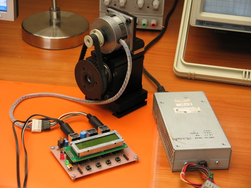
And here are the finished parts.

Black anodizing gives a cool look. The belt I had at hand was a bit more than the required length, and making a padding block was more cheap than buying a new belt.


The circuit
The motor was nema23 size, 4 volt ! 1 amp. I designed a board around a PIC16F628, using a simple cmos motor driver scheme. Minidin connectors were used for power, motor and serial port (I hate db9 ones).

To drive the motor in half step mode, a minimum of 2 amps were required, and a power supply I got from an old ethernet switch some years ago was handy. Tough the 5 volt line has a nominal 5 amp capacity, the voltage drops to 4 volts when the motor is energized (two coils), so chopping was not required. 12 volts line was used to feed a 5v regulator for the logic.
I write the pic program in assembly, a bit tedious work, but the final code was pretty. The system work this way:
- Button 1: step forward
- Button 2: step backward
- Button 3: step size decrease
- Button 4: step size increase
- Buttons 3,4 (at the same time): reset.
- Backlight on 3 seconds after a button is pressed.
Here is the set.
I plan to build a plastic box at some time, as a small chips from the lathe can roast the board.
Preparing
Before using the indexer, some stuff was needed:
- A support arbor: I modify a taig arbor to support small gears.
- A cutting tool: I don’t like the sherline gear cutting tool, so made one that uses small hand made inserts.
- A reference center to calibrate headstock Z axis.
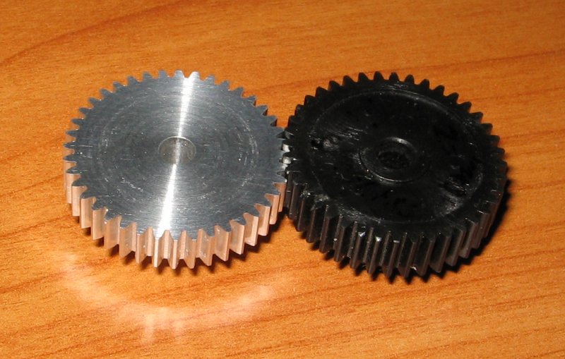
- A plastic gear used as pattern to make the cutting inserts: I choose one from my bag of scrap gears.
- The virgin gear part.

The cutting tool I’ve made support two inserts, so this way shape imprecisions in the inserts are canceled a bit (at least in theory). To make the inserts, a 3/16″ tool blank is grinded until, in front of some light, the cutter match the plastic gear. Then the tip of the tool bit is cutted with a dremel cutting wheel. A small grinding wheel can help to give final finish.

As noted in the image, I’ve done and extra insert, to do a prior cutting before using the shape-matched ones, saving my hard-to-made gear cutters from wearing.
The choosed pattern gear has the following parameters:
- m = 0.6 (metric “module”)
- Z = 40 (tooth number)
- Pitch diameter = Dp = m*pi*z =
- Pitch diameter = m*z/2 = 24
- Outside diameter Do = D + 2m = 25.2
- Tooh depth = ht = 2.2 * m = 1.33 (there are slight variations of this formula)
Module was deducted using the formula m = Do / (Z + 2). In this case, measured outside diameter was 5.21, giving m = 0.6. Note that if the module has more than one decimal may be it be a inch gear. I found that there are no business standard in scratch gears; sometimes two gears that seems to be compatible at first doesn’t match at all when you take measurings. Please note that the pitch diameter is important as states the distance beetwen two mate gears: for pitch diameters D1 and D2, there must be an inter-axis distance of D1/2 + D2/2.
A First Gear
The first step was to fix the Z axis using the center.

Later, the blank gear is centered in the arbor using a dial indicator. This is tedious, as when you tighten the screw, the blank easily get out of center.
Here is the first cutting pass. Cutting was a lot more soft than what I expected.

After the this prior cut, final inserts are installed and the Y axis is calibrated. Cutter-blank distance is reseted, and several rounds are done until reach the 1.33mm calculated advance. Note that both inserts must reach the same distance from the spindle axis, so this requires to fix one and adjust the other using some reference surface.

An here is the result. Not bad. Deburring of front cutting side was done using a knife, something a bit difficult (second image).

A simple verification: the size of two engaged gears must be 25.2+25.2-1.2= 49.2. Actual value is around 49.25, so it appears there was a slight oversize; then I took another measuring, using two small steel rods: the plastic gives 25.05, and the metal 25.01. So it appears that is the plastic the oversized one, at least in part.


Of course this isn’t a high precission high endurance gear, but it’s great for the hobbist.
Overall
Making gears this way requires a lot of setup time, but the whole process is pretty simple: calibrate, set cutting depth, go forward and backward, rotate a step, go forward, etc. I do several rounds, but now I think that for this gear size only two rounds are required: a heavy and a finish cut, using the same inserts. Also I think that only one good shaped insert will do the work.
As mentioned, a critical point here is the shape of the cutting tool, so this method will work only if you have enough skills to give your cutting tool the gear tooth shape. As an alternative, you can buy gear cutting modules, but these are costly and one unit covers only a range of tooth (z) at one pitch size (m).
Note the with this method you can’t make a reduction gear from a single piece; for this, you have to make two assembly pieces. Anyway, reduction can be provided by the motor, so that’s not a issue.
One of my to-do things in my list is automate my mill, something that will decrease tooth cutting time to a breeze.
That wasn’t an easy work. The short way would had to buy the Sherline rotary table or indexing tool. Anyway, the tool works fine, at least for small gears. A now doing a gears seems to be a really easy task to me.
Update: source code here (you need MCP from microchip).

Way cool! Thanks for sharing! Awesome site!
Thank you very much for sharing your talent here.
I really want to make some gears. You give me some ideas. What kind of tool bits did you use for it? I would like to make one myself.
Tool bits are made of 3/16 HSS shaped with an ordinary 4″ bench grinder and a dremel, and cut to length at the end. Original plastic gear was used as template to check fit. I remember make of three tools bits take me around one or two hours; the first was a bit over-grind, so for the two others I was careful and go slow. Hope this helps.
how small can you go with this lathe, will work with wrist watch gears? i need to
I don’t know anything about watch repair, but to me wrist watch gears look way tiny.
Can i download the pic program?
firmware/source code for the divider? IS it FREE?
Sure. Once I find the source I will add a link (in a week or so).
TNX!
Sory for the molestation. You have not yet found the source?
Finally sort my mess and find the source. Sorry for the delay.
Hello, metalAddict!
I was interested in firmware / source code for the divider.
Perhaps you have already found this information?
Sorry for the molestation!
impecable…!
Great design! I’m delighted! Is it possible to place the PCB pattern? Thanks in advance!
Wow, nice design.
Can you tell the taig part numbers. I would like to use this spindle in my design but not clear what parts to order. You say that you order “Taig lathe spindle, arbor and mounting”. Specially I am curious about the part that connects the spindle with the mill table, is it from Taig?
Many thanks for your help
Javi
Cool. Thanks for sharing.
Awesome job! You have one hell of skills man!
Check out my plan, i need some recommendations
Im going to make the 4th axis just like yours except it will be designed to fit in to the vise for quick installation. Also it could be mounted horizontally as well as in angular position.
I hate installing stuff so maybe the chucking method will be useful?
What do you think?
Ah, two things i see in your system, it seems that mounting the motor in top will interfere with z axis, maybe mounting it away from the z might help. Also get a chuck! 🙂
I also hate doing setup work, but every time I go the lazy way I end repenting. Chucking would be nice, rigidity is the only to worry. I did my setup thinking in just cutting gears; I did choose the taig spindle because it is cheap (please note I can also rotate it around the vertical axis). So my setup may be not as good as a general purpose 4th axis, and mounting the motor on the side would possibly be a better option. Good luck with your project!.
Cool and clean
Great design! I’m delighted! Is it possible to place the PCB pattern? Thanks in advance!
Sorry! Dear metalAddict, Please place link to the PCB pattern! Thanks in advance!
Sorry for the delayed response. I put Eagle files and pic source (mplab) here: https://www.dropbox.com/s/5p638py9d4ah4w8/indexer.zip?dl=0 . I wasn’t able to fin the .hex file, but this can be generated using MPLAB; as this was done with a rather old version, I guess source files should be imported into a new project. Good luck.
This is a great instructable! Only one annoying issue: change all the “tough” to “though” which is the word you’re really searching for! Minor point (and I apologize if English is your 2nd or third language. It’s my first and only fluent language 😉 )
Otherwise, very well done.
Thanks for sharing this.
Nitrous
Thanks! I really appreciate any correction to my poor English.
Thank you very much! I so lazy to design a PCB.
I will repeat your design!
I just forgot… pins for PIC ICSP programing aren’t in the standard order, so you should be careful or use an external programmer.
A Jim dandy MACHINE but a bit over my head ?.